MAS 863: How to Make (Almost) Anything
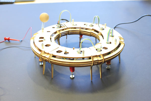
It's a dance dance robot. Tap dance performence envolves lots of people dancing on stage. The requirements of tempo accuracy make it perfectly to be computaionized. There are several aspects of the concept.
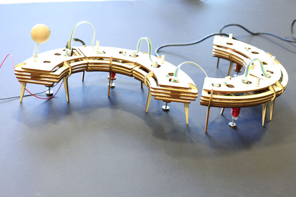
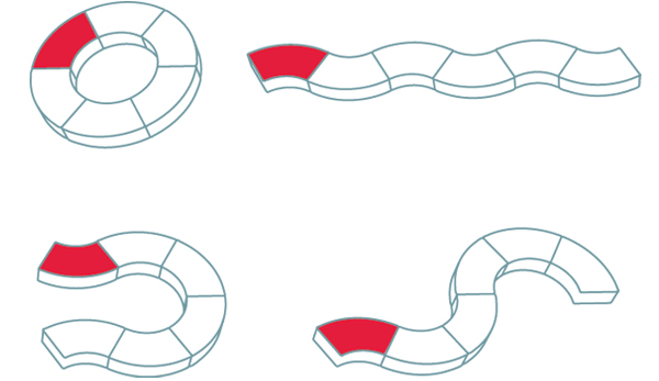
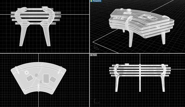
1. Reconfigurable: each module includes one leg, and the legs can be arranged freely to form different geometies.
2. Adjustable/Composable: The tempo of each leg can be adjusted via a rotaionary button. Six together can form a harmony rhythm.
3. Pre-designed mode: through a on-screen interface, player can select different tap dance mode, and compose movements in real time.

holes on the boards are cutted on Modela while milling out the circuit board. Some careful measurement and designed is needed in order to get the position of holes right in order to attach to board to the top piece of laser cutted wood top. As laser cut is fast anyway, try and adjust the file based on the circuit board if it didn't work at the first try.
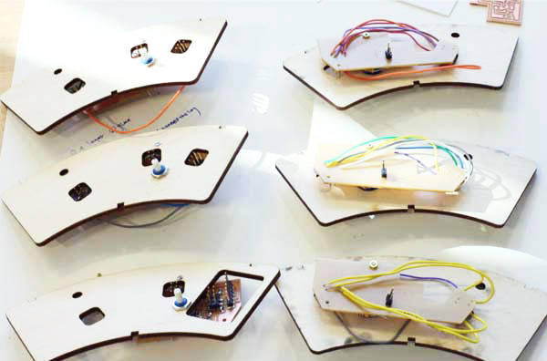
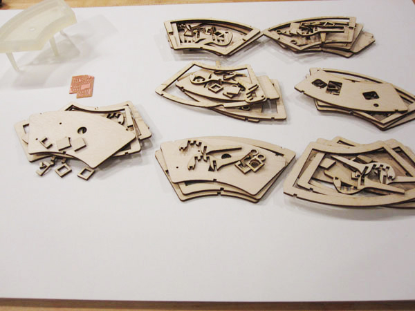
I used 1/8'' marine plywood for the case. One consideration of selecting wood rather than acrylic is that in case of slight mistakes in cutting, I could easily glue some parts, or sand some edges when I try to press fit different pieces.
Holes are designed to firstly, assemble boards; secondly, leave space for flexible cable connections;
The parts I used include:
1/4'' acrylic tube to hole the wires;
magnects wires;
medal stick as legs;
magnets as feet;
rubber caps;
A great tutorial on making and controlling solenoid:
http://www.nerdkits.com/videos/robotic_xylophone/
Some tips:
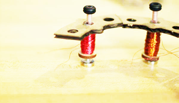
- To wind hundreds of magnet wires around the acrylic tube, you could either use your hand, or use a hand drill/lathe;
- Loops are friends; more loops, larger electrical magnet force;
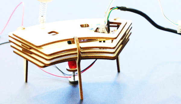
- To enhance the magnet force, I attached a small magnet at the bottom of the metal stick which is driven up when the electricity is on. Luckily, the cylinder magnet looks like foot, which is aligned with the project topic of tap dancing;
-The solenoid I made can be powered by 8 ~ 12v. If I keep the voltage at 8v, and each high signal sent out through microcontroller lasts for 40milisecond, the solenoid barely became hot, which is good.
-The magnet wire is covered with insulation; For connection on both end, you have to get the insulation layer off with knife.
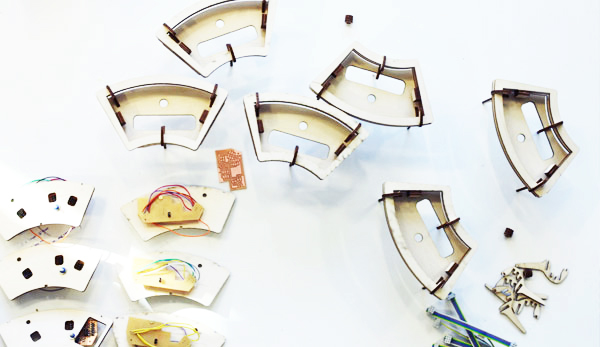
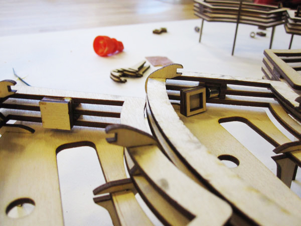
As each units have two sides, and I wanted to make sure each side can be connected with any side of the other unit, so I designed a box on each side that can just allow the small magnet to flip and rotate. So when sides from different units are approaching, the magnet from each box with flip automatically to attract each other.
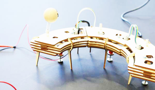
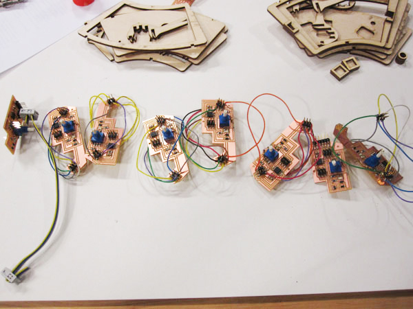
Three kinds of cables are used in the project. And holes were left there for flexible connections: positive and GND high voltage power connection with the bridge; FTDI cable with the bridge; 6 lines rainbow cable to connect two unit (if the two units are connected clockwise, rainbow cable are align the same direction; otherwise, flip the cable for connections)
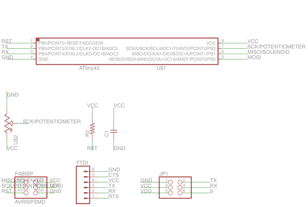
The system includes one bridge and five nodes boards. All six boards have similar basic components, which include anolog input from potentiometer, digital output to solenoid, serial communication and power supply. The only difference is, the bridge unit is connected with computer through FTDI cable, and in charge of communicate the serial information from the computer to himself and the other five nodes.
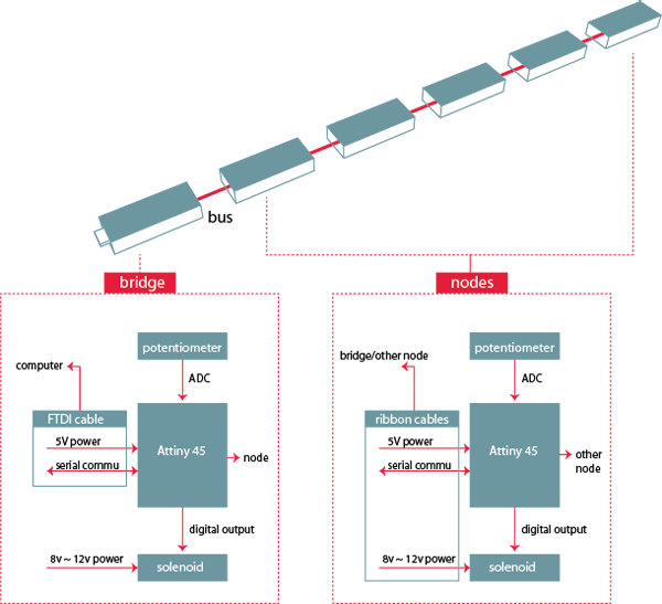
As we can see from the schematic, the microcontroller I chose is Attiny 45. Potentiometer is connected with 5V power and a 200ohm resistor, while the anolog output is connected with ADC1 pin of Attiny 45; The version I posted here has a voltage regulator, to make sure Attiny 45 get 5v power while solenoid can get more power (FTDI cable can give 5V for microcontroller as well, in that case we could get rid of voltage regulator);
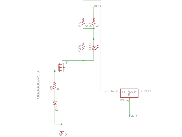
From Schematic Part 2, the way to control solenoid is shown. MOSFET is connected with a digital output pin of Attiny45, in order to control the high voltage(8~12v) to go through the solenoid; two parts are critical, the first is: we need a diode (in my case a LED to utilize the wasted power to blink) in parallel with the solenoid; the second is: when MOSFET is connected to ground, we need another diode in parallel.
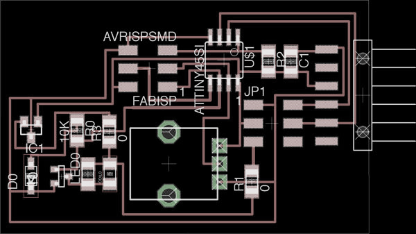
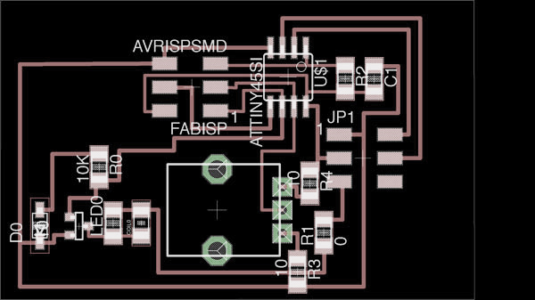
As I printed out one layer board, I threw some 0ohn resistor to jump over some lines.
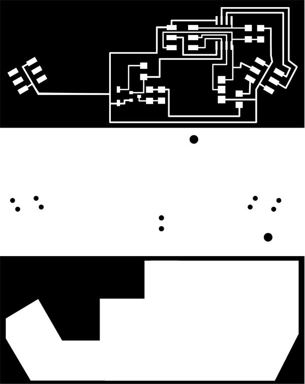
I used eagle to design the board, and export the black and white png image under 1000dpi. I connected some pins from below the board, hense I drew holes in photoshop; I've modified the shape of the board as well, to fit the mechanical design for the convenience of assembling; Finally the boards are milled out in Ronald Modela with 1/64''for the traces and 1/32'' bit for the hole and cutout.
<Download>:
eagle file for bridge with voltage regulator
eagle file for nodes
milling files for origional eagle file
milling files modified for being longer
An interface was built in Processing with some pre-built patterns of tap dances. It talks with the hardware through serial communicaiton.
Players can select one pattern and repeat the action, or they can put different pattern in a line and compse their own tap dancing movements.
Special thanks to:
Neil's enormouse courage, passion to work on this project;
David Millis and Brian's help on Serial communication/checking, making fuse, etc.
Adam's help on Eagle design and Terminals;
Moriz and Shahar's help on baud rate, serial communication;
Skylar's support on Modela tutorial and logistics;
David Constanza's tutorials on laser cut machine, shopbot machine;
Daneil's suggestion and inspiration on Solenoid.